PDFracture Analysis
Next-generation simulation of crack initiation and propagation — fully in the cloud. Peridynamics naturally handles discontinuities, modelling crack growth, branching, and merging without remeshing or special crack tracking.
Overview
Advanced fracture mechanics through a powerful but easy-to-use cloud-based workflow. Peridynamics naturally handles discontinuities — making it ideal for modelling crack initiation, growth, branching, and merging, all without remeshing or special crack-tracking techniques.
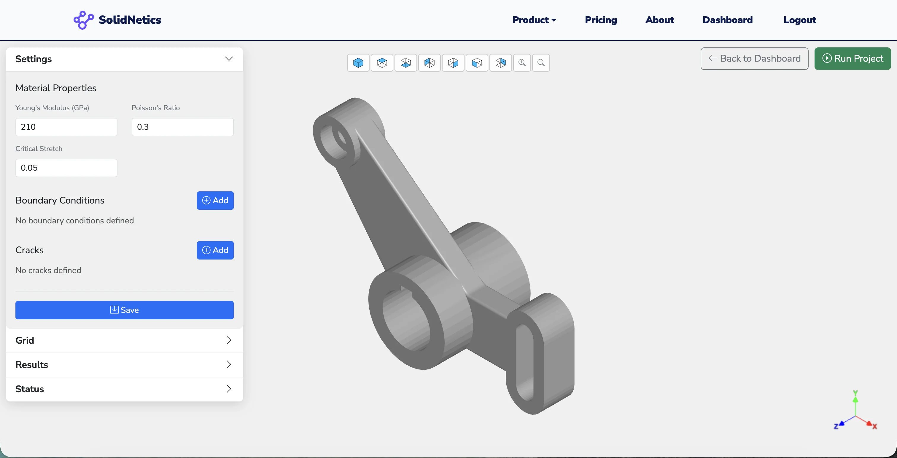
Direct CAD ingest
STL, STEP and IGES files import directly. Optional predefined planar cracks placed visually on the part.
Implicit PD
An efficient implicit peridynamic solver for quasi-static problems — no special crack tracking, no remeshing as cracks evolve.
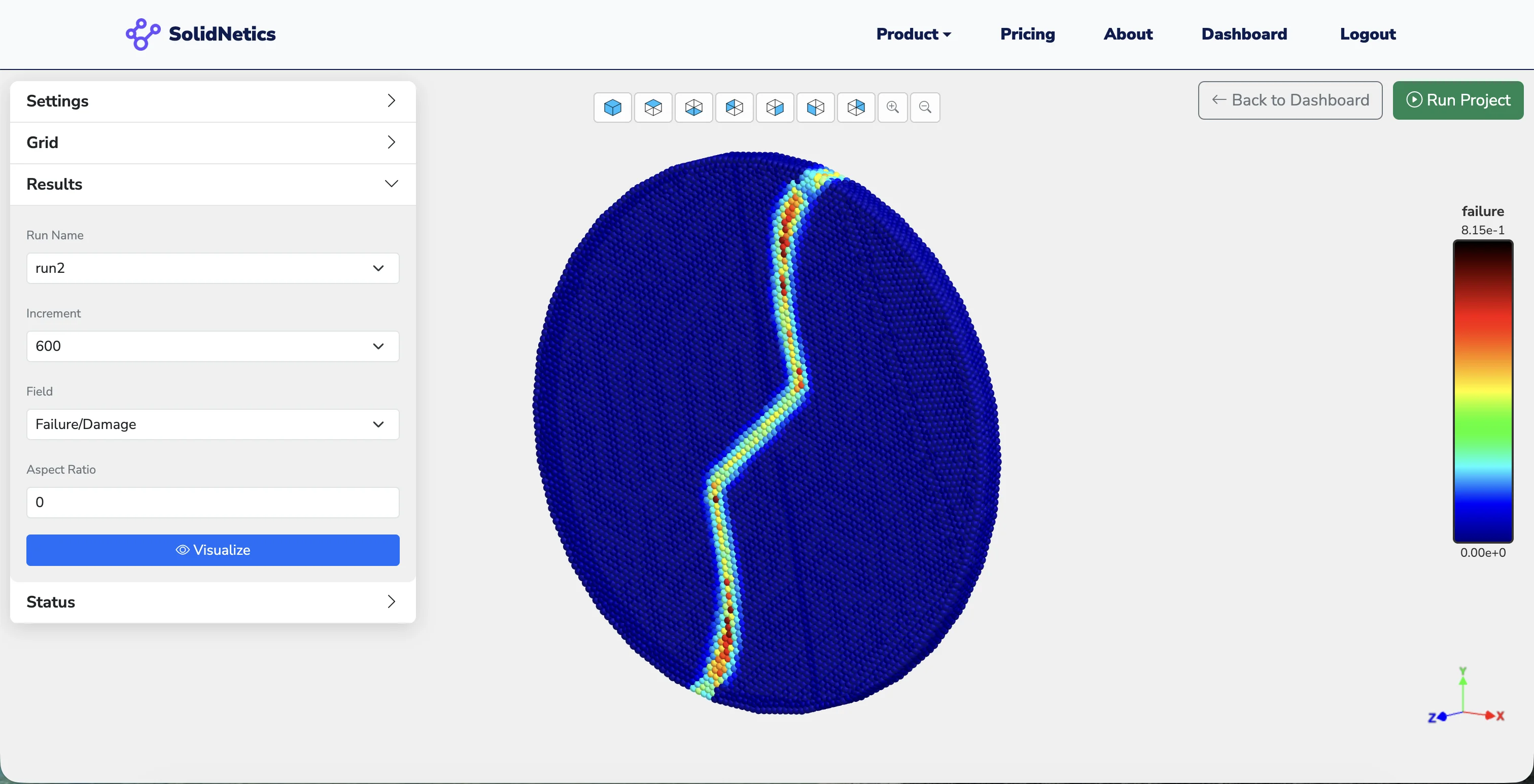
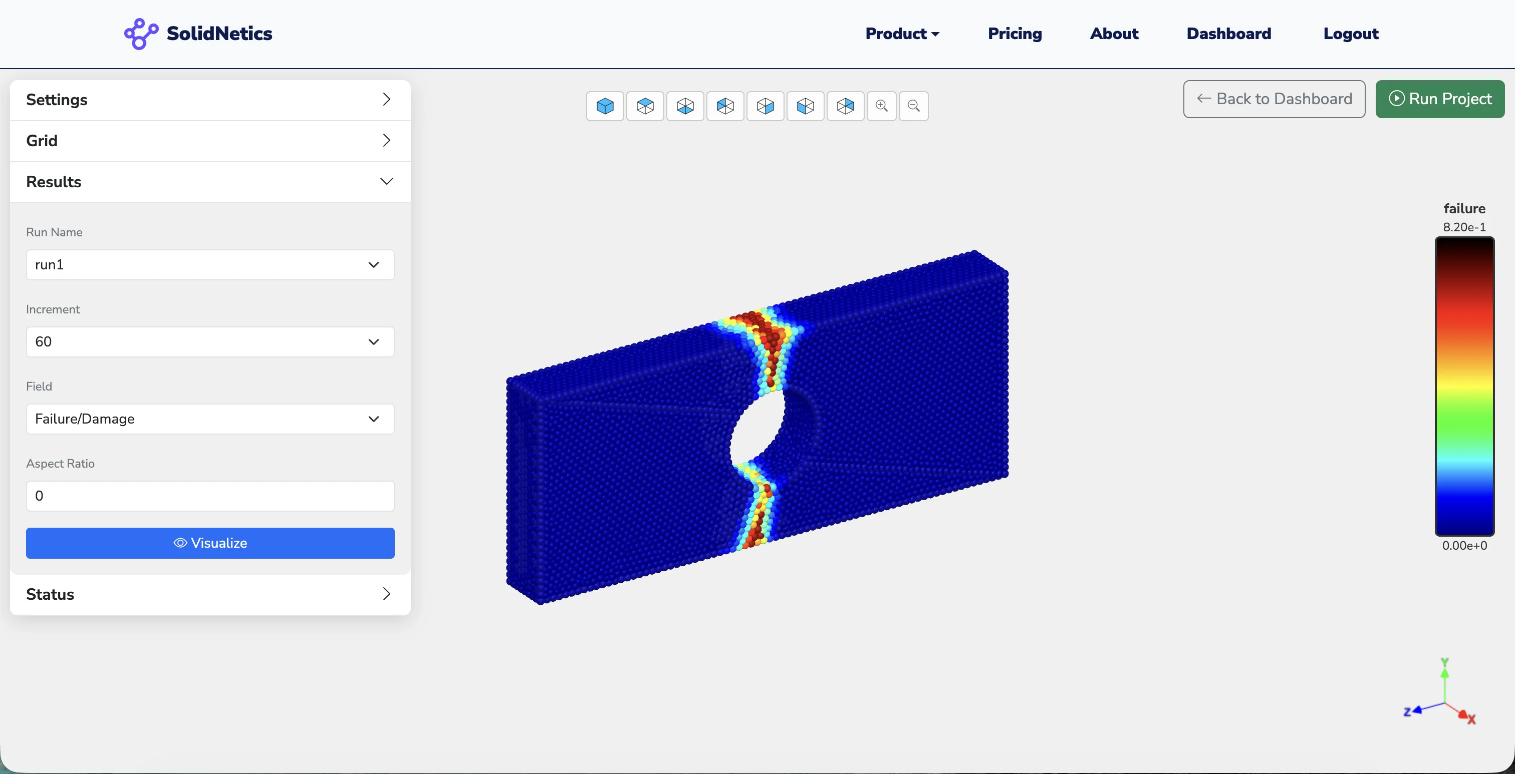
Damage & cracks
Damage maps, crack patterns, displacement and stress fields — visualised in 3D, ready to interpret.
Why Peridynamics
Traditional FEM struggles with discontinuities — element distortion, mesh dependence, special crack-tip enrichments. Peridynamics is formulated on bond integrals over a non-local horizon, so cracks emerge naturally from the physics without any extra machinery.
Capabilities
Six features that make peridynamic fracture practical for everyday engineering work.
Implicit peridynamic solver for quasi-static problems
An efficient implicit solver, purpose-built for fracture in solids:
- Implicit time integration for stable quasi-static loading
- Bond-based peridynamic formulation with critical stretch failure
- No special crack-tip enrichment, no XFEM bookkeeping
- Damage emerges from bond breakage — physically motivated
Incremental loading framework
Load is applied in steps, with crack propagation tracked between each:
- Step-by-step loading with adjustable increments
- Per-step damage evolution & crack-pattern updates
- Solver convergence monitoring at each step
- Captures both stable and unstable crack growth regimes
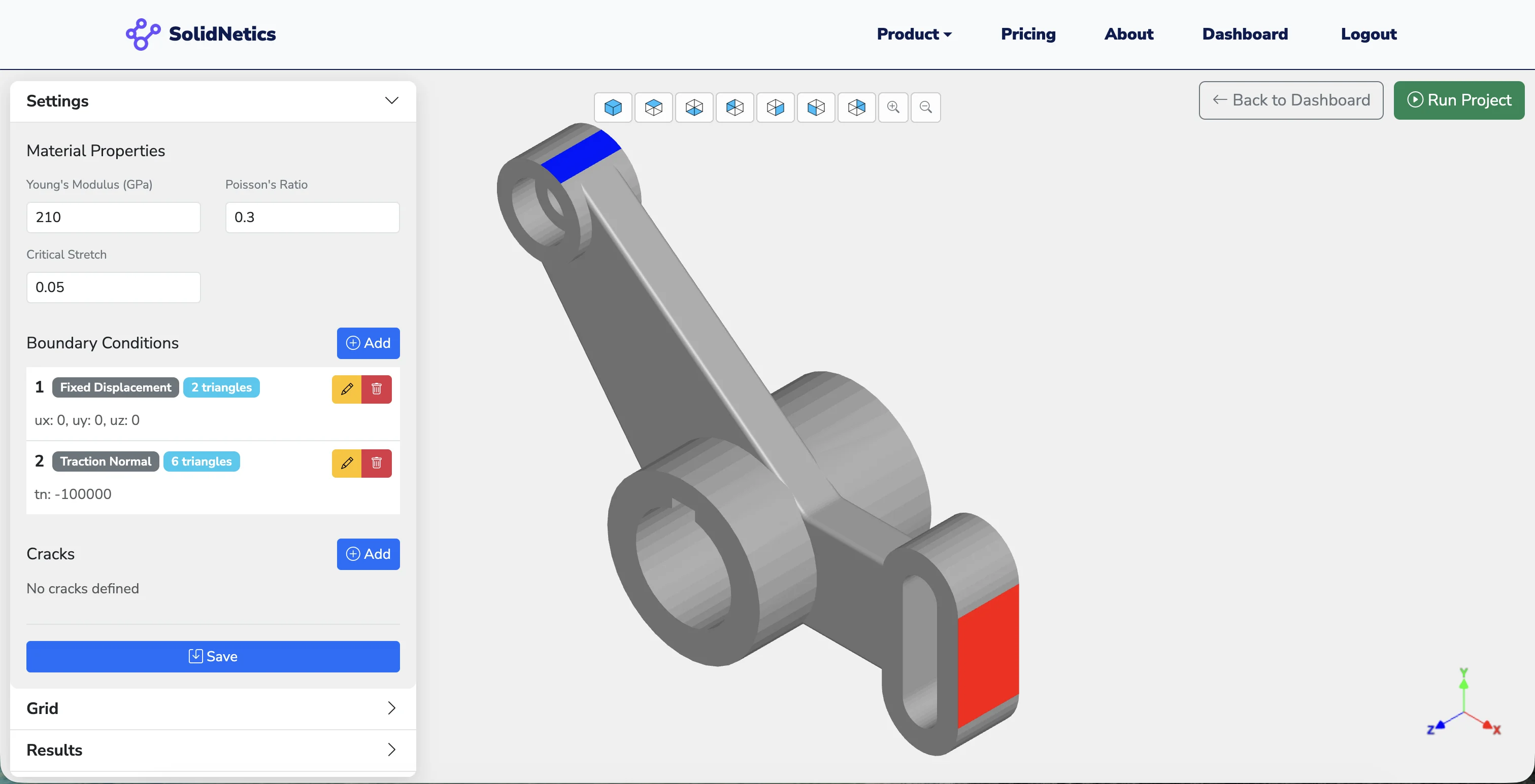
Flexible boundary conditions
Visual BC assignment on CAD surfaces and edges — no manual node selection:
- Displacement (prescribed, fixed, symmetry)
- Traction / pressure on surfaces
- Line loads on edges, lumped forces at vertices
- Automatic normal detection for traction direction
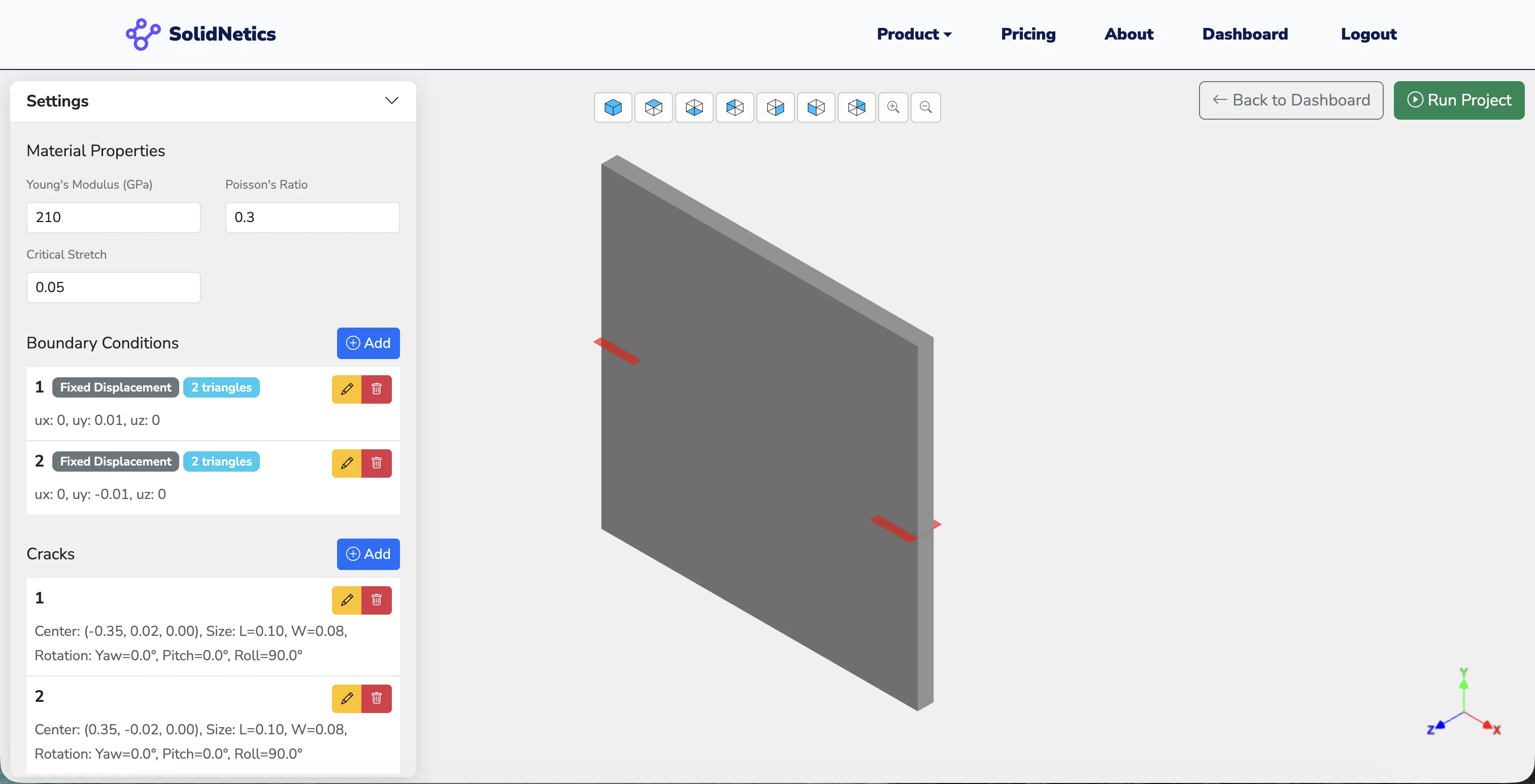
Predefined planar cracks
Seed cracks in the part to study propagation from a known starting point:
- Place planar cracks visually on the geometry
- Initial bond-breakage applied along the crack surface
- Multiple cracks per part, each with its own orientation
- Investigate branching, merging, and coalescence from initial defects
Direct CAD integration
The same CAD pipeline used across the SolidNetics stack:
- STL, STEP, IGES file support
- Automatic peridynamic point cloud generation from the geometry
- Adjustable point density for resolution control
- Multi-body parts & complex geometries
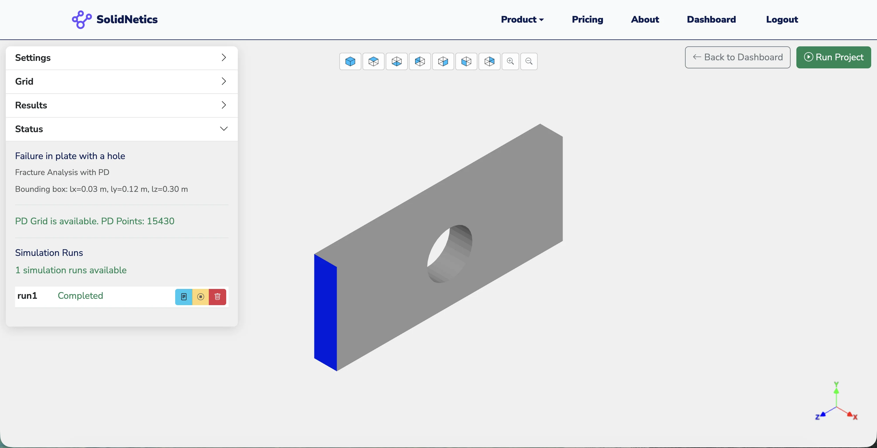
Powered by high-performance cloud computing
Bond-based PD is compute-heavy. SolidNetics scales it elastically:
- Multi-processing engine on high-core cloud workers
- Per-project & per-run resource scaling
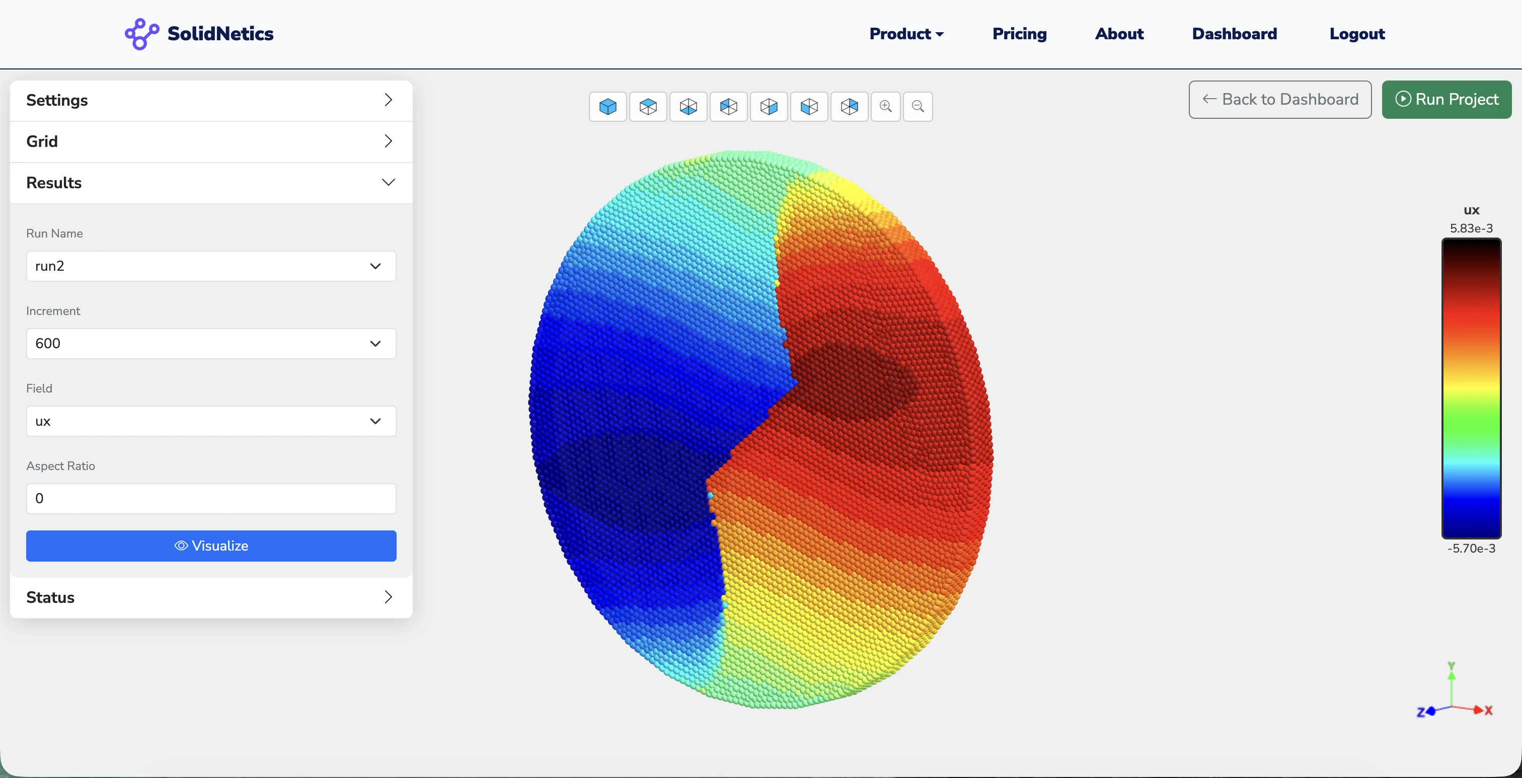
- 3D post-processing — damage maps, displacement, stress, Von Mises
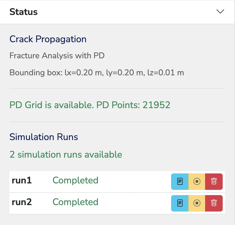
- Status dashboard with run progress & compute time
3D post-processing for fracture
Full visualisation of damage evolution, crack patterns, and stress fields — in the browser, with no local GPU requirement.
Why cloud-based fracture
No installation. No licensing servers. No workstation needed. Peridynamic fracture solves run on SolidNetics cloud infrastructure.
Multi-processing engine
Bond integrals parallelise naturally — scaled across high-core cloud instances on demand.
Access from anywhere
Windows, Mac, Linux, tablets, even lightweight laptops. Your fracture projects travel with you.
Always up to date
New material models, post-processing fields, and solver improvements roll out automatically.
Designed for ease of use
Three steps from CAD upload to a full fracture simulation result.
Upload & seed cracks
Drop in STL / STEP / IGES, set material, place predefined planar cracks if needed.
Generate grid & assign BCs
Automatic peridynamic point cloud, visual boundary-condition assignment on surfaces.
Run & visualise online
Implicit PD solve under incremental loading, damage & crack patterns streamed to your browser.
Applications
Ideal for structural integrity assessment, damage evolution studies, brittle and quasi-brittle failure analysis — across aerospace, civil, energy, and academic engineering.
Watch the cracks grow — in the cloud
Predict crack initiation, propagation, branching, and merging without remeshing or special crack tracking. Peridynamics, simplified.